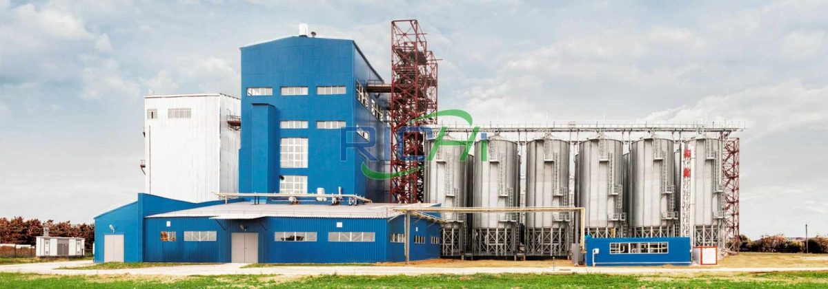
This is a 6t/h fish feed mill in Brazil project. The client was originally a livestock and poultry feed processing plant.
Brazil is one of the fastest growing countries in aquaculture in the world, with an annual growth rate of about 5-8%. The main aquaculture species (tilapia, catfish, shrimp) rely on artificial feed. Brazil plans to double its aquatic production by 2030 (currently about 800,000 tons/year), and the demand for feed will surge simultaneously. For investors, Brazil is one of the most promising markets in the field of fish feed in South America.
Based on this background and the company’s development needs, the client decided to expand the aquatic feed production line in the vacant land in the northeast corner of the project.
After the completion of the fish feed mill plant project, the annual production scale of 50,000 tons of aquatic feed can be achieved. At the same time, during this expansion process, a 6-ton natural gas boiler (equipped with a low-nitrogen burner) will be added according to environmental protection requirements. The original 4-ton natural gas boiler will be equipped with a low-nitrogen burner and used as a standby boiler. The factory currently has a labor quota of 40 people, including 15 management personnel and 25 production personnel. This renovation and expansion project will add 15 new labor quotas. The working hours are 330 days, with three shifts and 8 hours per shift.
Product plan
After completion, the fish feed mill in Brazil project can achieve an annual production scale of 50,000 tons of aquatic feed. The product plan is detailed in the table below.
| No. | Product Name | Output (10,000 tons/year) | Remarks |
| 1 | Extruded Fish Feed | 4 | The production process and raw and auxiliary materials of adult fish feed and small fish feed in this project are the same, and the proportions of individual raw and auxiliary materials are slightly different |
| 2 | Extruded Small Fish Feed | 1 |
Project content and scale
This fish feed mill in Brazil project is built in the existing factory area. A new aquatic feed workshop with 6 floors in the main body and 2 floors in part will be built in the northeast corner of the factory area, and related public auxiliary projects and environmental protection projects will be built as supporting facilities. The project content is detailed in the table below.
| Engineering Category | Engineering Name | Engineering Content and Scale |
| Main engineering | Aquatic Feed Workshop | The main part is 6 floors and part is 2 floors, with a construction area of 7656 m2. It is divided into raw material warehouse (first floor), finished product warehouse (second floor), raw material receiving system, first crushing system, first batching and mixing system, ultrafine crushing system, second batching and mixing system, puffing drying and spraying system, puffing finished product packaging system, powder recovery system and supporting auxiliary systems. It can achieve an annual production scale of 50,000 tons of special aquatic feed |
| Existing feed production workshop | The main production workshop has one underground floor and 5 floors above ground, with a construction area of 2,135 square meters, mainly including: primary cleaning section, crushing section, ingredient mixing section, granulation section, packaging section, etc., and has achieved an annual production scale of 60,000 tons of animals | |
| Auxiliary engineering | Office dormitory building | Located in the southeast corner of the factory, it is mainly used for office, accommodation and dining in the factory |
| Boiler room | A new 6-ton natural gas boiler is added, and the original 4-ton natural gas boiler is used as a backup boiler. | |
| Storage and transportation engineering | Aquatic feed raw material area | The aquatic feed raw material area is located on the first floor of the second floor of the aquatic feed workshop, and is equipped with various solid raw material storage and 2 20t oil storage tanks |
| Aquatic feed finished product area | The aquatic feed finished product area is located on the second floor of the second floor of the aquatic feed workshop | |
| Existing feed raw material area | The existing feed raw material warehouse is located on the north side of the factory area, with a single-story light steel structure and a construction area of 4,860 square meters | |
| Existing feed finished product area | The existing feed finished product warehouse is located on the south side of the factory, with a single-story light steel structure and a construction area of 2,430 square meters | |
| Existing raw material silos | Three raw material silos are set up in the middle of the factory, all with a specification of 2,000 tons | |
| Woven bag warehouse | Located on the north side of the canteen, used to store woven bags | |
| Tool warehouse | Located on the north side of the canteen, used to store tools | |
| Public engineering | Power supply system | The plant is equipped with a power distribution room. There is one transformer with a specification of 1250KVA, and a new 1600KVA transformer |
| Water supply system | The living and production water in the plant is provided by the local water supply network. | |
| Drainage system | The project separates rainwater and sewage. Domestic sewage relies on the existing septic tank and grease trap, and is discharged to the municipal sewage network after pretreatment. | |
| Gas supply system | The natural gas used by the boiler of this project is provided by the local gas supply network. A new 6-ton natural gas boiler is added, and the original 4-ton natural gas boiler is used as a backup boiler. |
Production equipment
The main production equipment of this fish feed mill in Brazil project is detailed in the table below.
| No. | Equipment name | Model or parameter | QTY |
| 1. Raw material receiving system | |||
| 1101 | Feeding hopper and fence | Feeding port: 1600×3500 | 1 |
| 1102 | Pulse dust collector | TBLMF27 | 1 |
| 1103 | Fan | 4-72-3.6A | 1 |
| 1104 | Scraper conveyor | TGSS25 | 1 |
| 1105 | Self-cleaning bucket elevator | TDTG50/28 | 1 |
| 1106 | Drum Primary cleaning screen | TQCY100 | 1 |
| 1107 | Pulse dust collector | TBLMF4 | 1 |
| Blower | 4-72-2A-0.75 | 1 | |
| 1108 | Permanent magnetic cylinder | TCXT25 | 1 |
| 1109 | Pneumatic Tee | TBDQ2X25X30O | 1 |
| 1110 | Scraper Conveyor | TGSS25 | 1 |
| 1111 | Pneumatic Tee | TBDQ2X25X30O | 1 |
| 1112 | Rotary distributor | TFPX10-250 | 1 |
| 1201 | Feeding hopper and fence | Feeding port: 1600×3500 | 1 |
| 120 2 | Pulse dust collector | TBLMF27 | 1 |
| 1203 | Fan | 4-72-3.6A | 1 |
| 1204 | Scraper conveyor | TGSS25 | 1 |
| 1205 | Self-cleaning bucket elevator | TDTG50/28 | 1 |
| 1206 | Cone powder screen | SCQZ90*80*110 | 1 |
| 1207 | Pulse dust collector | TBLMF4 | 1 |
| Blower | 4-72-2A-0.75 | 1 | |
| 1208 | Permanent magnet tube | TCXT25 | 1 |
| 1209 | Rotary distributor | TFPX14-250 | 1 |
| 2. Primary crushing system | |||
| 2101 | Crushing bin | Total 160m3 | 8 |
| 2102 | Upper level device | Rotary type | 8 |
| 2103 | Lower level device | Rotary type | 8 |
| Air hammer | AH-60 | 8 | |
| 2104 | Pneumatic gate | TZMQ40X40 | 8 |
| 2105 | Buffer hopper | / | 1 |
| 2106 | Impeller feeder | TWLY25*111 | 1 |
| 2107 | Pulverizer | SFSP66*100D | 1 |
| 2108 | Pulse dust collector | TBLMF63 | 1 |
| 2109 | Manual butterfly valve | 450 | 1 |
| 2110 | Crushing air duct | / | 1 |
| 2111 | High-pressure fan | 6-30-6.4A-22KW | 1 |
| 2112 | Silencer | Φ750 | 1 |
| 2113 | Sedimentation chamber | 3m3 | 1 |
| 2114 | Material sealing screw conveyor | TLSSF32 | 1 |
| 2115 | Self-cleaning bucket elevator | TDTG50/28 | 1 |
| 2116 | Rotary distributor | TFPX10-250 | 1 |
| 2205 | Buffer hopper | / | 1 |
| 2206 | Impeller feeder | TWLY 25*111 | 1 |
| 2207 | Crusher | SFSP66*100D | 1 |
| 2208 | Pulse Dust Collector | TBLMF63 | 1 |
| 2209 | Manual butterfly valve | / | 1 |
| 2210 | Crushing air duct | / | 1 |
| 2211 | High pressure fan | 6-30-6.4A-22KW | 1 |
| 2212 | Silencer | Φ750 | 1 |
| 2213 | Sedimentation Chamber | 3m3 | 1 |
| 2214 | Material Sealing Screw Conveyor | TL SSF32 | 1 |
| 2215 | Bucket elevator | TDTG50/28 | 1 |
| 2216 | Rotary distributor | TFPX10-250 | 1 |
| 3. primary batching and mixing system | |||
| 3101 | Batching silo group | Total about 450m3 | 28 |
| Squid paste silo | Total about 30m3 | 2 | |
| 3102 | Upper level device | Rotary type | 30 |
| 3103 | Lower level device | Rotary type | 30 |
| 3104 | Air hammer | AH-60 | 20 |
| 3105 | Warehouse discharging machine | TWLL20 | 4 |
| Arch discharging machine | PWLL25 | 2 | |
| Warehouse discharging machine | TWLL25 | 10 | |
| Storage machine | TWLL32 | 14 | |
| 3106 | Batching scale | 1500KG/batch | 1 |
| Sensor | PST1000kg | 3 | |
| Batching scale door | CM600X600 | 1 | |
| 3107 | Pneumatic butterfly valve | DN500 | 1 |
| 3107.1 | Pneumatic butterfly valve | DN3 00 | 1 |
| 3108 | Squid paste feeding port | / | 1 |
| 3109 | Pneumatic gate | TZMQ50*50 | 1 |
| 3110 | Single axis Paddle mixer | SJHS2 | 1 |
| 3111 | Buffer bin | 2m3 | 1 |
| 3112 | Air hammer | AH-60 | 1 |
| Level meter | Rotary type | 1 | |
| 3113 | Scraper conveyor | TGSS25 | 1 |
| 3114 | Self-cleaning bucket elevator | TDTG50/28 | 1 |
| 3115 | Buffer bin | 3m3 | 1 |
| 3116 | Vibration motor | / | 1 |
| Material level indicator | Rotary type | 1 | |
| 3117 | Outlet machine | TWLL25 | 1 |
| 3118 | Crusher | SFSP66×60 | 1 |
| 3119 | Pulse dust collector | TBL MF39 | 1 |
| 3120 | Manual butterfly valve | / | 1 |
| 3121 | Crushing air duct | / | 1 |
| 3122 | High pressure fan | 6-30-6.4A-15KW | 1 |
| 3123 | Silencer | Φ500 | 1 |
| 3124 | Sedimentation Chamber | 3m3 | 1 |
| 3124 | Material sealing screw conveyor | TLSSF32 | 1 |
| 3126 | Pneumatic tee | TBDQ2X25X30O | 1 |
| 3206 | Batching scale | 150 0KG/batch | 1 |
| Sensor | PST1000kg | 3 | |
| Batching scale door | CM600X600 | 1 | |
| 3206.1 | Pneumatic butterfly valve | DN500 | 1 |
| 3207 | Batching scale | 1500KG/batch | 1 |
| Sensor | PST1000kg | 3 | |
| Batching scale door | CM600X600 | 1 | |
| 3207.1 | Pneumatic butterfly valve | DN500 | 1 |
| 3208 | Pneumatic butterfly valve | DN300 | 1 |
| 3209 | Pneumatic butterfly valve | DN300 | 1 |
| 3210 | Pulse dust collector | TBLMF4 | 1 |
| Fan | 4-72-2A-0.75 | 1 | |
| 3211 | Small material feeding port | / | 1 |
| 3212 | Pneumatic gate | TZMQ40*40 | 1 |
| 3213 | Buffer hopper | / | 1 |
| 3214 | Pneumatic gate | TZMQ50*50 | 1 |
| 3215 | Recheck scale | 250kg/p | 1 |
| Pressure sensor | 100kg/pcs | 3 | |
| Batching scale door | CM40*40 | 1 | |
| 3216 | Pneumatic butterfly valve | DN300 | 1 |
| 3217 | Pneumatic tee | TBDQ2X25X30O | 1 |
| 3218 | Dual-shaft paddle mixer | SLHSJ4 | 1 |
| 3219 | Buffer bin | / | 1 |
| 3220 | Air hammer | AH-60 | 1 |
| Level meter | Rotary type | 1 | |
| 3221 | Scraper conveyor | TGSS25 | 1 |
| 3222 | Self-cleaning bucket elevator | TDTG50/28 | 1 |
| 3223 | Pneumatic tee | TB DQ2X25X30O | 1 |
| 3224 | Permanent magnetic tube | TCXT25 | 1 |
| 3225 | Rotary distributor | TFPX6-250 | 1 |
| 4. Ultrafine Grinding System | |||
| 4101 | Crushing Bin | A total of about 80m3 | 6 |
| 4102 | Loading Leveler | Rotary Resistance Type | 6 |
| 4103 | Material leveler | Rotary type | 6 |
| 4104 | Pneumatic hammer | AH-60 | 6 |
| 4105 | Pneumatic gate | TZMQ50×50 | 6 |
| 4106 | Buffer hopper | / | 3 |
| 4107 | Ultrafine pulverizer | SWFL150 | 3 |
| 4108 | Silencer | / | 3 |
| 41 08+1 | Ultra-fine wind net | / | 3 |
| 4109 | Rotary paddle discharger | Φ1500 | 3 |
| 4110 | Air shut-off device | TFGY25 | 3 |
| 4111 | Pulse dust collector | TBLMY128 | 3 |
| 4112 | Air shut-off device | TFGY25 | 6 |
| 4113 | Manual butterfly valve | / | 3 |
| Pneumatic butterfly valve | / | 3 | |
| 4114 | High pressure fan | TLGF-HY-55-1A | 3 |
| 4115 | Muffler | Φ900 | |
| 4116 | Enclosed square screen | FSFJ125 | 3 |
| 4116+1 | Scraper conveyor | TGSS25 | 3 |
| 4117 | Pneumatic tee | 3 | |
| 4118 | Pneumatic Tee | TBDQ2X25X30O | 1 |
| 4119 | Buried Scraper Conveyor | TGSS25 | 1 |
| 5. Secondary batching and mixing system | |||
| 5101 | Batching silo group | Total about 65m3 | 6 |
| 5102 | Upper level device | Rotary resistance type | 6 |
| 5103 | Lower level device | Rotary resistance type | 6 |
| 5104 | Air hammer | AH-60 | 6 |
| 5105 | Warehouse discharging machine | TWLL32 | 6 |
| 5106 | Batching scale | 3000KG/batch | 1 |
| Sensor | PST1000kg | 3 | |
| Batching scale door | CM700X700 | 1 | |
| 5107 | Pneumatic butterfly valve | DN300 | 1 |
| 5108 | Pneumatic butterfly valve | DN500 | 1 |
| 5109 | Small material feeding port | / | 1 |
| 5110 | Pneumatic gate | TZMQ40*40 | 1 |
| 5110.1 | Buffer bucket | / | 1 |
| 5110.2 | Pneumatic gate | TZMQ50*50 | 1 |
| 5111 | Double-shaft paddle mixer | SLHSJ4 | 1 |
| 5112 | Buffer bin | 3m3 | 1 |
| 5113 | Air hammer | AH-60 | 1 |
| Leveler | Rotary type | 1 | |
| 5114 | Scraper conveyor | TGSS25 | 1 |
| 5115 | Self-cleaning bucket elevator | TDTG50/28 | 1 |
| 5116 | Pneumatic tee | TBDQ2X25X30O | 1 |
| 5117 | Permanent magnetic tube | TCXT25 | 1 |
| 5118 | Buffer bin | / | 1 |
| 5119 | Material level device | Rotary type | 1 |
| 5120 | Double hole discharger | TXX2-60×20 | 1 |
| 5121 | High square screen | FSFGⅡ1*6*100 | 2 |
| 5122 | Scraper conveyor | TGSS25 | 1 |
| 6. Extrusion & Drying & Spraying System | |||
| 6101 | Waiting for Expansion Warehouse | 15+10m3 | 3 |
| Warehouse Manhole | / | 3 | |
| 6102 | Loading Leveler | Rotary Resistance Type | 3 |
| 6103 | Under level device | Rotary type | 3 |
| 6104 | Air hammer | AH-60 | 2 |
| 6105 | Bottom discharger | / | 2 |
| Out of warehouse | TWLL32 | 2 | |
| 6106 | Drum Feeding Silo | TXLP120 | 2 |
| 6107 | Feeding Auger | TWLY25 | 2 |
| 6108 | Dual Shaft Differential Conditioner | SBTZ39 | 2 |
| Single-shaft conditioner | HRTZB500 | 2 | |
| 6109 | Twin-screw extruder | HR145*2 | 2 |
| Steam pipeline and control system | / | 2 | |
| On-site water tank | / | 2 | |
| 6110 | Density controller | ECS360 | 2 |
| Hot water insulation device | Matching density controller | 2 | |
| 6111 | Shakron | φ650mm | 2 |
| 6112 | Air shut-off device | TGFYZ5 | 2 |
| 6113 | Centrifugal fan | 4-72-3.2C-3kw | 2 |
| Dehumidification duct | / | 2 | |
| 6114 | Brake Dragon | φ650mm | 2 |
| 6115 | Air Shutoff | TGFYZ5 | 2 |
| 6116 | Centrifugal Fan | 4-72-3.2C-3kw | 2 |
| Dehumidification Duct | / | 2 | |
| 6117 | fish feed Dryer machine | HRHG10000(2BW)-8 | 2 |
| Steam Pipeline and Control System | / | 2 | |
| 6118 | Shock Dragon | 2*D1500 | 2 |
| 6119 | Air shut-off device | TGFYZ9 | 3 |
| Drying air duct | / | 2 | |
| 6120 | Manual butterfly valve | 650 | 2 |
| 6121 | Centrifugal fan | 4-72-8C-22kw | 2 |
| Muffler | Φ1000 | 2 | |
| 6122 | Self-cleaning bucket elevator | TDTG50/28 | 2 |
| 6123 | Grading screen | SFJH130X2C | 2 |
| 6124 | Waiting for spraying | / | 2 |
| 6125 | Upper level device | Rotary type | 2 |
| 6126 | Lower level device | Rotary type | 2 |
| 6126 | Lower level device | Rotary type | 2 |
| 6127 | Brake Dragon | φ650mm | 2 |
| 6128 | Air Shutoff | TGFYZ5 | 2 |
| 6129 | Centrifugal Fan | 4-72-3.2C-3kw | 2 |
| Dehumidification duct | / | 2 | |
| 6130 | Multi-stage gate | ZMD40*40 | 2 |
| 6131 | Vertical sprayer | HRYTP2000 | 2 |
| Discharge gate valve | 40 0 | 2 | |
| Grease adding machine | SYTZ30 | 2 | |
| Grease adding machine | SYTZ30 | 2 | |
| Liquid scale | SYPCA30 | 2 | |
| Electronic control system | / | 2 | |
| 6132 | Buffer bin | / | 2 |
| 6133 | Loading level device | Rotary type | 2 |
| 6134 | Eccentric air shut-off device | TGFY30 | |
| 6135 | Flip-type cooler | SWLN28X28 | 2 |
| 6136 | External rotating brake | 2*D1400 | 2 |
| 6137 | Air shut-off | TGFYZ9 | 3 |
| 6138 | Cooling air duct | / | 2 |
| 6139 | Cooling fan | 4-72-8C | 2 |
| 6140 | Muffler | Φ1000 | 2 |
| 6141 | Belt conveyor | TDSL500 | 2 |
| 6142 | Self-cleaning bucket elevator | TDTG50/28 | 2 |
| 6143 | Rotary distributor | TFPX4-250 | 2 |
| 7. Expanded material finished product packaging system | |||
| 7101 | Finished product warehouse | A total of about 80M3 | 8 |
| Warehouse manhole | / | 8 | |
| 7102 | Upper material level device | Rotary resistance type | 8 |
| 7103 | Lower material level device | Rotary resistance type | 8 |
| 7104 | Air Dynamic gate | TZMQ40X40 | 8 |
| 7105 | “Fool” grading screen | SFJH140X2C | 2 |
| 7106 | Storage machine | TWLL20 | 2 |
| 7107 | Buffer bin | / | 2 |
| 7108 | Loading level device | / | 2 |
| 7109 | Electronic packaging scale for granular materials | DCS-50CS-P5 | 2 |
| 7110 | Belt conveyor bag sewing machine | / | 2 |
| 7111 | Scraper conveyor | TGSS25 | 2 |
| 7112 | Grading screen | SFJH140X2C | 2 |
| 7113 | Belt conveyor | TDSL500 | 1 |
| 7114 | Pulse dust collector | TBLMy16 | 1 |
| 7115 | Air shut-off device | TGFYZ7 | 1 |
| Dust removal duct | / | 1 | |
| 7116 | Centrifugal fan | 4-72-4.5A | 1 |
| 8. Powder recovery system | |||
| 8101 | Powder return bin | Total 5m3 | 2 |
| 8102 | Loader | Rotary type | 2 |
| 8103 | Loader | Rotary type | 2 |
| 8104 | Pneumatic gate | TZMQ40X40 | 2 |
| 8105 | Scraper conveyor | TGSS20 | 1 |
| 8106 | Self-cleaning bucket elevator | TDTG40/23 | 1 |
| 8107 | Scraper conveyor | TGSS20 | 1 |
| 8108 | Pneumatic tee | TBDQ2X25X30O | 1 |
| 10. Auxiliary production system | |||
| FZ01 | Grease adding machine | SYTZ30 | 3 |
| FZ02 | Liquid scale | SYTC150 | 1 |
| FZ03 | Air compressor | / | 2 |
| FZ04 | Filter | 1.5M3 | 1 |
| FZ05 | Gas storage tank | 1.0M3 | 3 |
| FZ06 | Freeze dryer | / | 1 |
| FZ07 | Boiler | 6t | 1 |
| FZ08 | Electric hoist | 5T | 1 |
| FZ09 | Grease storage tank | 20T | 2 |
Raw and auxiliary materials and energy consumption
The main raw and auxiliary materials and energy consumption of this fish feed mill in Brazil project are shown in the table below.
| Category | No. | Name | Annual consumption (tons) | Proportion (%) |
| Raw and auxiliary materials | 1 | Corn | 3000.263 | 6 |
| 2 | Flour | 6000 | 12 | |
| 3 | Soybean meal (CP46) | 9500 | 19 | |
| 4 | Rapeseed meal (imported double low) | 14000 | 28 | |
| 5 | Domestic fish meal (shrimp) | 400 | 0.8 | |
| 6 | Peanut meal | 3000 | 6< /td> | |
| 7 | Cottonseed meal (CP46) | 3000 | 6 | |
| 8 | Sprayed corn husk | 1000 | 2 | |
| 9 | Biological feed S | 1000 | 2 | |
| 10 | Rice bran | 2500 | 5 | |
| 11 | Rice DDGS | 2300 | 4.6 | |
| 12 | Bentonite | 500 | 1 | |
| 13 | Calcium dihydrogen phosphate | 1000 | 2 | |
| 14 | Soybean lecithin oil (internal addition) | 1150 | 2.3 | |
| 15 | Soybean oil (external spray) | 750 | 1.5 | |
| 16 | Sodium chloride | 140 | 0.28 | |
| 17 | Rubineng | 10 | 0.02 | |
| 18 | Dadekuai | 25 | 0.05 | |
| 19 | Lysine (70) | 150 | 0.3 | |
| 20 | Choline chloride 60% | 75 | 0.15 | |
| 21 | Yeast hydrolyzate type IV NX100 | 50 | 0.1 | |
| 22 | M5115 | 250 | 0.5 | |
| 23 | V5124 | 200 | 0.4 | |
| Energy | 24 | Natural gas | 100,000 m3/a | / |
Process design of fish feed mill in Brazil
The production process of this fish feed mill in Brazil project is mainly divided into ten sections. The detailed process flow is as follows:
- Raw material reception: Raw materials that need to be coarsely crushed (such as fish meal, cake meal and other large-particle raw materials) are put into the feeding hopper and then transported to the crushing bin through the elevator. Raw materials that do not need to be coarsely crushed are directly transported to the corresponding batching bin. A pulse dust collector is set separately at the feeding port to reduce dust.
- Raw material coarse crushing: Raw materials that need to be coarsely crushed need to be crushed by a crusher before entering the batching bin, and the particles pass through a 2.00mm sieve.
- First mixing: The ingredients are automatically batched through the central control system according to the formula table. The static accuracy of the batching scale is 1‰ and the dynamic accuracy is 5‰. Various solid additives are put into the small material feeding port. After the ingredients are batched, they are stirred and mixed in a double-shaft paddle-type high-efficiency mixer. The stirring time is generally about 5 minutes, and the coefficient of variation of the mixing uniformity is ≤7%.
- Ultrafine grinding: After the first mixing, the material is sent to the ultrafine grinder for ultrafine grinding. After ultrafine grinding, the material is screened and magnetically separated before entering the second mixer.
- Second mixing: While the material enters the secondary mixer, liquid additives, internal oils, etc. are added according to the required amount, and the second stirring and mixing begins. The stirring time is generally about 5 minutes, and the coefficient of variation of the mixing uniformity must be ≤7%.
- Tempering, puffing, and granulation: The evenly mixed material enters the conditioner and is tempered by controlling the amount of water and steam added. The tempering temperature is above 90 degrees, and the moisture content after conditioning is about 26%. Then it is sent to the floating fish feed extruder machine to start extrusion.
- Drying: The newly made feed pellets are sent to the dryer for drying. The temperature control is determined according to different feed varieties and particle sizes. The moisture content of the product meets the standard requirements of the customer company.
- External spraying of grease: After the feed is dried, it enters the differential weight liquid sprayer for external oil spraying, and the spraying is required to be uniform.
- Cooling and screening: After the oil spraying is completed, it enters the cooler. This fish feed mill in Brazil adopts a countercurrent cooler. Then, the corresponding screen is selected according to the product category for screening and enters the finished product warehouse.
- Packaging: The finished product packaging system includes an electronic packaging scale and a belt conveyor sewing machine, which can accurately and quickly complete the finished product packaging.
General layout
The plant area of this fish feed mill in Brazil project has a total of 1 raw material workshop and 1 finished product workshop. The main feed production workshop and 2 raw material silos are built between the two workshops. The living area is arranged in the southeast corner of the plant area, and the boiler room and other auxiliary rooms are arranged on the east side of the plant area. The aquatic feed workshop to be renovated and expanded is arranged in the northeast corner of the plant area, relying on the existing raw material silos for raw material pretreatment. The interior of the aquatic feed workshop is arranged horizontally and vertically in strict accordance with the requirements of the process, and each dust-generating point is equipped with a dust collector.
Since the process flow of this project is highly correlated and the semi-finished products also have a strong internal designated flow direction, the relevant production workshops and auxiliary workshops are mostly arranged nearby, which is conducive to the transportation of materials and shortens the transportation route.
In summary, the general layout plan has the characteristics of smooth process flow, convenient transportation within the field, and power and auxiliary production facilities as close to the load center as possible. In addition, the main power equipment is arranged in the center of the plant area, which can effectively reduce the impact of power noise on the acoustic environment of the plant boundary. Therefore, the general layout of this project is reasonable.
Why is it suitable to build a fish feed mill in Brazil?
There are many advantages and potentials in building a fish feed mill in Brazil, mainly based on the following key factors:
1. Rich aquatic resources and mature aquaculture
The world’s leading aquaculture country: Brazil is the largest fish producer in Latin America, and the scale of freshwater aquaculture (such as tilapia, catfish, shrimp) and marine aquaculture continues to expand, and there is a strong demand for fish feed.
Superior natural conditions: The Amazon Basin and numerous freshwater lakes provide an ideal environment for aquaculture, and feed supply is the core link of the industrial chain.
2. Adequate raw material supply
Advantages of a large agricultural country: Brazil is one of the world’s largest producers of soybeans and corn (soybean meal and corn are the main sources of protein and energy for fish feed), which can reduce the cost of raw material procurement and transportation.
Abundant animal by-products: By-products (blood meal, bone meal) of the meat processing industry (such as poultry and beef) can be used as feed additives to improve resource utilization.
3. Market demand growth
Domestic consumption upgrade: With population growth and increased awareness of healthy eating, Brazil’s per capita consumption of aquatic products has increased year by year, driving the expansion of the aquaculture industry.
Export potential: The demand for Brazilian farmed fish in South America and the global aquatic market (such as the United States and Europe) has increased, indirectly stimulating the demand for feed.
4. Policy and infrastructure support
Government incentives: Brazil encourages investment in agriculture and aquaculture through tax incentives, subsidies and other policies, such as the “More Fisheries and Aquaculture” program.
Convenient logistics: The main aquaculture areas are close to ports (such as the north and northeast), which is convenient for the import of raw materials and the export of finished products; the inland transportation network (roads, rivers) is gradually improving.
5. Technology and cost advantages
Localized production reduces costs: reduces dependence on imported feed (currently some high-end feed still needs to be imported), and has stronger price competitiveness.
Technical adaptability: Special formulas can be developed for local fish species (such as tilapia) to improve breeding efficiency.
6. Sustainable development potential
Green energy: Brazil’s electricity is mainly hydropower, and the production cost is low-carbon and environmentally friendly.
Circular economy: The use of agricultural waste (such as bagasse) to develop biofeed is in line with the global sustainable trend.
Brazil’s agricultural resources, aquaculture scale, market demand and policy support make it a strategic choice for building fish feed production lines. Investors can focus on major aquaculture areas (such as Paraná, São Paulo or Amazonas), taking into account local supply and export markets, while using sustainable raw materials to improve competitiveness.
If you are interested in this fish feed mill in Brazil project, or want to build, expand or renovate a fish feed processing line, please feel free to contact RICHI MACHINERY to obtain information on the civil engineering plan, overall plant layout, process design, equipment configuration and quotation of the aqua feed production line!